Overview
CircuitGenome is structured around six modules, each addressing a different direction of the analog circuit design problem:
Topology Synthesizer (SYN) — constructs op-amp circuits from modular building blocks and emits SPICE netlists.
Subcircuit Recognizer (SR) — identifies structural subcircuits (differential pairs, cascode mirrors, etc.) in a flat SPICE netlist.
Functional Block Recognizer (FBR) — identifies the functional role of each part of a flat SPICE netlist (input stage, load, bias generation, etc.).
Sizer (SZ) — computes transistor W/L values that satisfy DC performance specifications (gain, GBW, phase margin, slew rate, CMRR), via either an analytical CP-SAT solver or a gm/Id lookup pipeline.
Designer (DES) — chains synthesis, sizing, and verification end to end to return designs that meet a target spec.
Visualizer (VIS) — an interactive Streamlit UI for browsing topologies and module variants as block diagrams.
Together they form a forward flow — synthesize → size, chained end to end by the Designer — alongside the inverse Recognizer that recovers a netlist’s structure, with the Visualizer for interactive exploration.
Topology Synthesizer (SYN)
The synthesizer models an op-amp as a composition of module slots. Each slot is filled by one module variant — a concrete circuit implementation of a functional category. The synthesizer iterates over all valid combinations and wires them together according to a topology template.
Main components
An op-amp is assembled from these functional categories:
Input pair — the differential input stage (PMOS/NMOS, optional source degeneration).
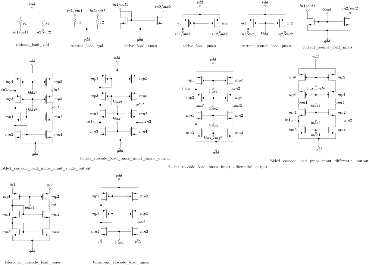
Load — the first-stage load (resistor, active current-mirror, current-source, folded / telescopic cascode).
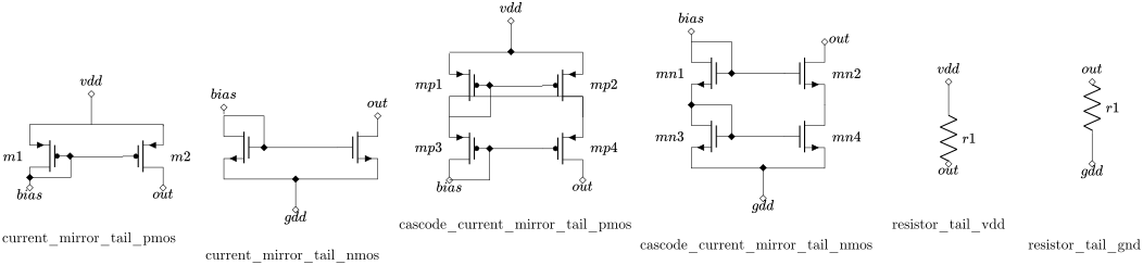
Tail current — the input pair’s bias current source (current mirror, cascode current mirror, resistor).
Bias generation — constructed per combination from what the other slots consume on each bias rail (not enumerated).
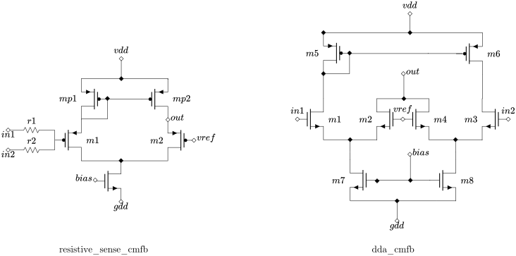
CMFB — common-mode feedback, present only for fully-differential loads.
Compensation — Miller capacitor, Miller cap with nulling resistor, or indirect compensation.
Amplification stage — the second / third gain stages (common-source or non-inverting current-mirror).
Output stage — a source-follower buffer, used in the
*_buffered_*templates.
Input pair

Load
Tail current
CMFB
Topology templates
Template name |
Stages |
Output type |
Compensation |
|---|---|---|---|
|
1 |
Single-ended |
— |
|
2 |
Single-ended |
— |
|
2 |
Fully differential |
— |
|
2 |
Single-ended |
— (+ follower |
|
2 |
Fully differential |
— (+ follower |
|
3 |
Single-ended |
Nested Miller (NMC) |
|
3 |
Single-ended |
Reversed Nested Miller (RNMC) |
|
3 |
Fully differential |
Nested Miller (NMC) |
|
3 |
Fully differential |
Reversed Nested Miller (RNMC) |
|
3 |
Single-ended |
Nested Miller (NMC) (+ follower |
|
3 |
Single-ended |
Reversed Nested Miller (RNMC) (+ follower |
|
3 |
Fully differential |
Nested Miller (NMC) (+ follower |
|
3 |
Fully differential |
Reversed Nested Miller (RNMC) (+ follower |
Circuits generated per template
The table below is a snapshot of enumerate_circuits run on each template
with the default configuration (unsupported and bias_infeasible
variants excluded). It is generated by tools/gen_topology_counts.py and
refreshed whenever the enumeration changes. For how each count arises — the
polarity / output-cardinality compatibility filtering, the parked-variant
tags, and the per-template derivation — see the Topology Synthesizer
module page.
Template name |
Circuits generated |
|---|---|
|
60 |
|
180 |
|
648 |
|
360 |
|
2,592 |
|
1,080 |
|
1,080 |
|
23,328 |
|
23,328 |
|
2,160 |
|
2,160 |
|
93,312 |
|
93,312 |
Total |
243,600 |
How to use it
Generate circuits from the command line with circuitgenome synthesize or
from Python. See CLI Usage and Python API for worked
examples, and the
Topology Synthesizer module page for the full
component catalogue, the enumeration and compatibility analysis, the
demand-driven bias construction, the modular interface contract, and the SPICE
output formats.
Subcircuit & Functional Block Recognizer (SR / FBR)
The recognizer is the structural inverse of the synthesizer: given a flat SPICE netlist, it recovers the modular building blocks that produced it.
What it does
It is organized as a 3-layer pipeline:
Netlist parsing (Layer 0) — reads the flat SPICE text back into a structured netlist of devices, external ports, and internal nets.
Subcircuit Recognizer (SR, Layer 1) — matches a library of structural patterns (differential pairs, current mirrors, cascode loads, bias legs) against the parsed devices and reports every matching candidate, leaving the disambiguation to the next layer.
Functional Block Recognizer (FBR, Layer 2) — assigns each recognized structure to its functional role, either against a known topology template (recovering the exact set of module variants) or topology-free (grouping the structures by functional block for a netlist of unknown origin).
Together, SR and FBR support round-trip recognition of every topology template the synthesizer produces.
How to use it
Recognize a netlist from the command line with circuitgenome recognize or
from Python. See CLI Usage and Python API for worked
examples, and the
Subcircuit Recognizer (SR) and
Functional Block Recognizer (FBR)
module pages for the netlist parser, pattern library, hooks, and the
topology-free disambiguation algorithm.
Sizer (SZ)
The sizer takes the FBR result (slot assignments) plus a performance specification and returns W/L values for every transistor in the circuit. It has two sizing paths — an analytical Level-1 CP-SAT solver and a gm/Id lookup pipeline, selected by technology — and supports every op-amp topology template the synthesizer produces.
Supported performance specs
The sizer solves against these DC performance targets, each a bound the sized circuit must satisfy:
Open-loop DC gain (minimum)
Gain–bandwidth product, GBW (minimum)
Phase margin (minimum)
Slew rate (minimum)
CMRR (minimum)
Quiescent power (maximum)
Output swing (minimum / maximum)
Alongside these targets you also give the sizer an operating point — supply rails, tail bias current, and load capacitance. See the Sizer (SZ) module page for the complete input specification.
How to use it
Size a circuit from the command line with circuitgenome size or from
Python. See CLI Usage and Python API for worked examples,
and the Sizer (SZ) module page for the sizing algorithm,
technology configurations, and SPICE verification.
Designer (DES)
The Designer is the spec-driven top layer: it chains the three lower modules end to end. Given a target performance specification, it enumerates every valid circuit for the chosen template(s), sizes each one, keeps only those whose SPICE-measured metrics meet the spec, and exports the survivors as sized netlists — turning a one-line specification into a set of ready-to-simulate op-amp designs.
What it does
End-to-end search — runs the full synthesize → size → SPICE-verify → export flow for every candidate, so you start from a spec rather than a hand-written netlist.
Spec-driven acceptance — keeps only the designs whose SPICE-measured metrics satisfy the target, and records why each rejected candidate failed.
Multi-template — searches across one or several topology templates in a single run, in parallel.
Ranked results — returns per-template statistics and the best design points, with the sized netlists written out for further simulation.
How to use it
Run the full flow from the command line with circuitgenome design. See the
Designer module page for the Python API and the
report structure.
Visualizer (VIS)
The Visualizer is an interactive Streamlit web UI for exploring the topology space by hand. It renders any topology and module-variant combination as a block diagram — and, for valid combinations, the assembled SPICE netlist — so you can see how the modular building blocks fit together without writing any code.
Two tabs
Topology Explorer — pick a topology and swap each slot’s module variant; the block diagram and netlist update live. Invalid combinations show why the synthesizer rejected them.
Module Browser — lists every module variant by category, with its ports and device count.
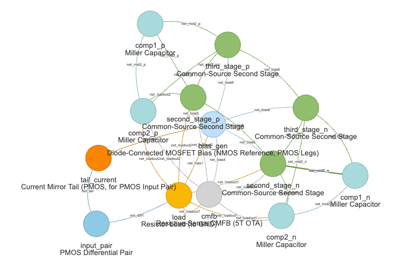
The Topology Explorer tab: pick a topology and module variants in the sidebar, and the block diagram updates live.
How to use it
Launch the Visualizer from the command line — see CLI Usage for how to
run it and the viz extra it needs.